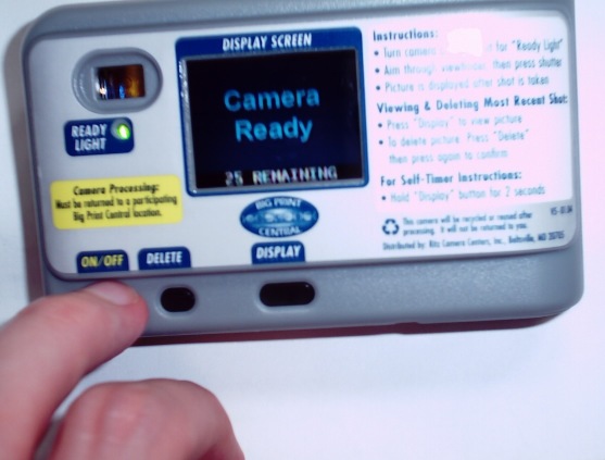
Dakota Digital PV2 (Red) Single-Use Digital Camera
Ritz loves us hardware hackers so much, they've gone ahead and released a new-and-improved version of the Dakota for us to play with. (All right, they also re-engineered it to make it more secure. Bah.) The most noticeable feature of the Red PV2 version is a color LCD panel on the back for picture review. (Unlike some digital cameras, the PV2 screen does not act as a live viewfinder; it only shows the picture after you've taken it.
It appears variants of the PV2 camera are showing up in other stores, such as CVS pharmacy. It sounds like there is a slightly different software variant (and possibly USB pinout) for each vendor, to prevent one from being able to 'process' cameras sold by another store.
Hackin' It
A new challenge is appreciated by all. Right now John Maushammer is hard at work disassembling the firmware, which he sssssucked out of the FLASH memory with a custom-built reader. This guy's got more dasm-fu in his pinky than I would have if there were 10 of me, so I'll be mostly staying out of the ARClite reversing for now, and see about building up a fun hack for the color LCD to publish. It might make a nice addition to my homebrew mp3 player.
Right now you can find all the magic happening on the Linux-hacker.net BBS (camera section). I won't be updating this page all the time with reduplications of what's posted on the BBS, so be sure to actually check it out. If you can't wade through all the up-to-the-minute excitement there (300+ posts in the old PV2 thread, and a new one growing fast!) several gurus (us mere mortals are hardly worthy to walk amongst them!) excellently summarize the progress so far:
http://www.maushammer.com/systems/dakotadigital/lcd.html Detailed analysis in progress of the firmware, USB command format and the compressed image format. Know ASM? Check out the V8 disassembler and the FIRMWARE.COMMENTS file packaged with it. (This is updated often, check back there for the latest version!). May also be a USB poking tool on the way for OSX.
http://www.digitalfluff.net/pv2/ Page of daBass, very active in the hacking efforts. On here is everything known about the .RAW image format used by the camera, and some extracted .RAW files (both normal pictures and e.g. all-white, with their corresponding previews) for analysis; also documentation of the .pack file format containing firmware used by similar SMaL cameras.
http://www.bluedonkey.org/cgi-bin/twiki/bin/view/Linux/DakotaPv2Camera Summary of USB information, experiments with drivers for several similar SMaL cameras, and usbtool, a USB poking tool for Linux.
http://cexx.org/dakota/usbpoker.zip My own (not entirely finished, barely documented, barely tested...fair warning!) bulk USB poking tool for Windows. Depends on libusb-win32 to do the dirty work. Here are some pre-written bulk command packets for basic tasks such as getting and sending keys to the camera and dumping the accessible memory.
PV2Tool and TFT viewer/converter - PV2Tool is a graphical Windows program that automates tasks such as unlocking a camera and downloading the flash memory, that would fast become tedious to do by hand (e.g. using the poking tool). The TFT viewer allows you to view and convert between native bitmap image format and a special image format used for the camera's LCD screen.
PV2Mod - a utility for MacOSX (only, for now) allowing the user to modify files on the camera, such as TFT images and even the FIRMWARE.BIN.
Scoping of the electrical signals to the CMOS image sensor - sort of a very rough guess at pinout.
Some dumps from my camera, model Ritz firmware 6410
Some basic statistics generated from extracted .RAW (image) files, and quick Matlab script to generate them
Controller
SMaL Camera Technologies
Numbering on controller chip:
AIC0021B
02TWN5103
C68051.00
Memory
16Mx8 NAND Flash memory: Samsung K9F2808UO8-YCB0
4Mx16 SDRAM: Micron Technologies MT48LC4M16A2TG-75E
Preliminary stuff of interest
The edge connector of the PV2 electrically matches that of the classic Dakota, at least as far as the USB pins go; whatever cable/contraption used to access the classic should work for this one without modifications.
Holding down ALL the buttons at once (shutter, Display, Delete) while turning on power will display a diagnostic screen showing the camera's serial number, firmware revision and similar information.
See John's PV2 page with an update for the PV2, including mucho documentation of the USB interface, firmware, authentication, processor memory map and more. Also, datasheets for the more interesting parts (including the LCD) and a gallery of good dissection photos. Just go there, dammit :-)
USB info
Here is the dump-out from SUCR commandline, walking thru the device properties. (All versions of SUCR do this, in case the manufacturer decided to get clever and move the devices/interfaces/endpoints/altsettings around). This gives a good idea of the 'organization' of the camera's USB interface.
usb_set_debug: Setting debugging level to 3 (on)
LIBUSB_DLL: usb_os_init: dll version: 0.1.8.0
LIBUSB_DLL: usb_os_init: driver version: 0.1.8.0
LIBUSB_DLL: usb_os_find_busses: found bus-0
LIBUSB_DLL: usb_os_find_devices: found \\.\libusb0-0003--0x058f-0x9254 on bus-0
LIBUSB_DLL: usb_os_find_devices: found \\.\libusb0-0004--0x0dca-0x0027 on bus-0
Looking at device with USB id 058F/9254
Looking at device with USB id 0DCA/0027
Found camera...
This device has 2 possible configuration(s).
Looking at configuration 0...This configuration has 1 interfaces.
Looking at interface 0...This interface has 1 altsettings.
Looking at altsetting 0...This altsetting has 2 endpoints.
Endpoint 0: Address 81h, attributes 02h (Bulk) (In)
Endpoint 1: Address 01h, attributes 02h (Bulk) (Out)
Looking at configuration 1...This configuration has 1 interfaces.
Looking at interface 0...This interface has 1 altsettings.
Looking at altsetting 0...This altsetting has 2 endpoints.
Endpoint 0: Address 81h, attributes 02h (Bulk) (In)
Endpoint 1: Address 01h, attributes 02h (Bulk) (Out)
Set config: 0
Found bulk endpoint 129 on Configuration 1 Interface 0 Altsetting 0
Set alt. interface: 0
[...]
The camera has 2 configurations, one is for 200mA and the other is for 100mA, but "seem" otherwise identical. (See the testlibUSB dump-out below for additional details.) When the configuration is set by SUCR, the camera emits a 2-tone ascending beep, and the LED comes on. Actual communication with the camera was found to use the Mass-Storage Bulk Only protocol.
Here is the output from testlibUSB:
DLL version: 0.1.8.0
Driver version: 0.1.8.0
bus/device idVendor/idProduct
bus-0/\\.\libusb0-0002--0x0dca-0x0027 0DCA/0027
- Manufacturer : SMaL
- Product : Digital Camera
wTotalLength: 32
bNumInterfaces: 1
bConfigurationValue: 1
iConfiguration: 3
bmAttributes: 80h
MaxPower: 100
bInterfaceNumber: 0
bAlternateSetting: 0
bNumEndpoints: 2
bInterfaceClass: 255
bInterfaceSubClass: 0
bInterfaceProtocol: 0
iInterface: 0
bEndpointAddress: 81h
bmAttributes: 02h
wMaxPacketSize: 64
bInterval: 0
bRefresh: 0
bSynchAddress: 0
bEndpointAddress: 01h
bmAttributes: 02h
wMaxPacketSize: 64
bInterval: 0
bRefresh: 0
bSynchAddress: 0
wTotalLength: 32
bNumInterfaces: 1
bConfigurationValue: 2
iConfiguration: 3
bmAttributes: 80h
MaxPower: 50
bInterfaceNumber: 0
bAlternateSetting: 0
bNumEndpoints: 2
bInterfaceClass: 255
bInterfaceSubClass: 0
bInterfaceProtocol: 0
iInterface: 0
bEndpointAddress: 81h
bmAttributes: 02h
wMaxPacketSize: 64
bInterval: 0
bRefresh: 0
bSynchAddress: 0
bEndpointAddress: 01h
bmAttributes: 02h
wMaxPacketSize: 64
bInterval: 0
bRefresh: 0
bSynchAddress: 0
Some dissection pictures
 Back of the PV2. The case is held together by 3 screws cleverly hidden beneath the sticker on the back - one to the left of the on/off switch, one to the left of the viewfinder, and one just beneath the 'recycle' logo at lower right. Feel around with your fingers and you'll find 'em easily enough.
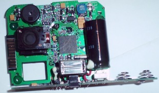 Front side showing the SMaL controller, lens (now with electronically-actuated cover), and high-voltage flash capacitor, the business end of which is exposed...so be careful. If you want to remove the LCD, one of the screws is partially beneath/behind the capacitor, so you'll have to sort of force it out of the way a bit.
Luckily, the USB edge connector doesn't appear to have changed.
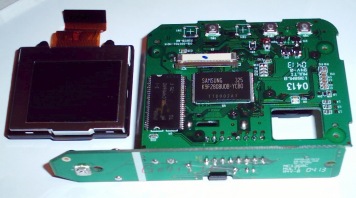 Back side of board, with LCD screen removed. There are places for 2 extra buttons, to the left and right of the Display button. 'Pressing' (shorting) the phantom switch SW1 while the camera is on causes it to beep 3 times, but no other effect is evident. (Of course, I haven't actually taken any pictures on it yet). Shorting SW4 doesn't seem to do anything. Holding SW1 while plugging the camera into a USB port and claiming the interface appears to enter a diagnostic mode - the two-tone beep is replaced with a single high-pitched beep, the USB interface behaves differently and the memory accessible via a known buffer overflow exploit remains (mostly) initialized to a working copy of the camera firmware, which can be read out this way if all else fails (but watch for randomly corrupted bits!).
(And yes, all the dissection photos are taken using the original (non-LCD) Dakota cam. That's almost disturbing when you think about it.)
Back to Dakota info